

How to design reasonable gear parameters
Classification:External cylindrical gear Author:ETAGEAR Published at:2016-12-31
How to Design Reasonable Gear Parameters
Author: Mao Guoxing, ETAGEAR Chief Gear Technology Officer
Recently, I saw a post on a gear forum discussing how to design reasonable gear parameters. Unfortunately, no one gave a detailed answer. Most replies suggested that there is no evaluation standard for gear parameters. This is indeed true, but we believe there is still room for discussion.
We are a gear design software company, and we feel obligated to share our gear design philosophy, hoping everyone can find reference on how to design reasonable gear parameters.
This article will explain how to design reasonable gear parameters in two sections:
- How to evaluate whether gear parameters are reasonable
Completeness of gear geometry
Machinability of the gear
Continuous transmission conditions
Smooth gear operation
Gear strength and life
Other requirements
Case analysis of forum parameters
How we determine evaluation standards.
How to evaluate whether gear parameters are reasonable
- Completeness of gear geometry.
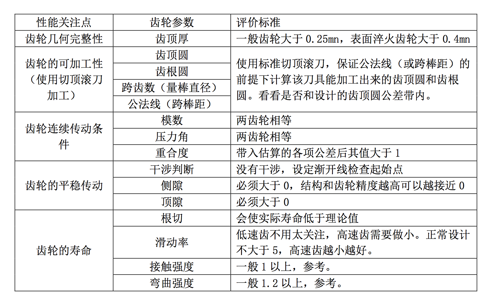
We believe that gear parameters all have physical meaning. The gear described by our designed parameters should be an actually existing object, not just parameters without a physical counterpart. In the gear design process, "tooth tip thickness" (tip tooth thickness) is an important indicator for evaluating geometric completeness. During design, we often encounter cases where the tip tooth thickness is negative. A negative tip tooth thickness means that the tip circle of your gear parameters cannot be machined. It indicates that the profile shift coefficient is too large — the two involute curves intersect before reaching the tip circle. Therefore, your tip circle can never be machined. Consequently, the contact ratio, sliding ratio, tip clearance, etc., calculated using this tip circle are all incorrect. At the same time, an overly pointed tooth tip is prone to chipping during mesh engagement and disengagement (just a tiny bit at the tip), and the debris entering the meshing tooth surface can easily cause gear wear. Therefore, for evaluating geometric completeness of gear parameters, we recommend checking the gear's "tip tooth thickness" and the corresponding imaginary rack cutter's tip tooth thickness. The former determines whether the tip circle can be machined, while the latter determines whether the root circle can be machined. The imaginary rack cutter's tip tooth thickness only needs to be checked when using non-standard gear design; gears machined with standard cutters do not need this check.
So how large should the tip tooth thickness be to be considered reasonable? The "Gear Handbook" recommends greater than 0.25mn for general gears, and greater than 0.4mn for surface-hardened gears. However, in our practical applications and reverse engineering, we have also found many gears with values smaller than these. So how should a company determine this value? Please see the second section.
Here we advocate using the software's mathematical model to calculate tip tooth thickness, rather than using line drawings or 3D modeling methods to judge whether it is appropriate. Mathematical models are more objective, and software evaluation is less error-prone. In practice, we have found many cases where tip circles could not be machined to dimension, all caused by negative tip tooth thickness. The parameter calculators all used 3D modeling to judge whether gear parameter design was good or bad. The naked eye cannot distinguish whether the tip circle is in position, and thinning of the tip is frequently overlooked.
- Machinability of the gear.
There are many gear processing methods, such as injection molding, powder metallurgy, precision forging, etc. There are also hobbing, gear shaping, gear shaving, gear grinding, and other machining methods. Different processing methods produce different gear accuracies, naturally having different requirements for gear parameters.
Mold-produced parts generally have few constraints on gear parameters, as long as demolding is not affected. Therefore, lead modification is generally not applied to mold-produced gears.
Machined gears are much more complex, involving rough machining and finish machining. Different combinations of rough and finish machining methods also cause subtle differences in gear parameters. Because there are many combination types, we will not discuss them in detail here. We will only discuss how to verify the machinability of parameters for the most common gear processing method today — gear hobbing.
Hobbing is the most widely used gear processing method. Generally, hobbing can achieve Grade 7 accuracy gears, and with good equipment and tooling, Grade 6 accuracy can be achieved. Gears obtained by hobbing typically drop one accuracy grade after heat treatment.
For gear hobbing, if you use a custom hob, generally as long as the geometric completeness of the gear is ensured, machinability will not be a problem. If you use a standard hob, then gear parameter design requires attention. First, in the current processing of small and medium module gears, factories basically use topping hobs to replace non-topping hobs.
What is a topping hob? Let us explain here. Previously, standard hobs (non-topping hobs) had both addendum coefficient and dedendum coefficient of 1.25. When you use such a hob to machine gears, the hob only cuts out the root circle. Because the gear's addendum coefficient is 1, the root of the hob does not participate in cutting. The gear's tip circle is obtained by precision turning before hobbing, then hobbing machines the tooth spaces. So a hob whose root does not participate in cutting the tip circle is a non-topping hob.
A topping hob naturally means the hob's root participates in cutting the gear. The gear's tip circle is machined by the hob's root. When using a topping hob, the gear blank's outermost diameter is not the tip circle diameter, but slightly larger, and then the hob completely forms the gear shape.
So why does everyone now use topping hobs to replace non-topping hobs? Let us understand the characteristics of both methods. Advantages of non-topping hobs: the machined gear's tip circle is obtained by turning or other machining methods, so its tolerance range can be set relatively small, and the contact ratio and sliding ratio do not change much within the tolerance range. Meanwhile, the tip circle can be adjusted within a certain range as needed without changing the hob parameters. Disadvantages of non-topping hobs: the center of the tip circle and the center of the tooth profile (center of the pitch circle) will not coincide. Because the tip circle is turned, and the tooth profile is hobbed. So when we finally use the tip circle for positioning to grind the bore, it often causes the radial runout Fr and cumulative pitch error Fp to be unstable due to the bore center and tooth profile center (pitch circle center) not coinciding, and sometimes causes accuracy to exceed tolerance. Factories that process gears have experienced this — if you measure Cpk for Fp, the Cpk values are basically always poor. Even changing fixtures and clamping at the tooth thickness position does not give ideal results. Using topping hobs can greatly improve this problem. Because the tip circle, pitch circle, and root circle are all cut by one hob in one operation, the concentricity when using the tip circle to position for bore grinding is much better, and Fp and Fr are significantly improved. So the biggest advantage of using topping hobs is that gear accuracy Fp and Fr can be improved. Similarly, its disadvantages are also obvious. Because the tip is cut by the hob, the tooth thickness tolerance basically determines the tolerance range of the tip circle. In general, the tip circle tolerance band is about 3 times the tooth thickness tolerance band. This causes the tip circle tolerance band to be larger than that of traditional hobs. When gears with few teeth (less than 6) use topping hobs, the contact ratio easily fails to meet requirements.
After all that discussion, how do we verify gear machinability? This requires verification based on your own gear processing technology. Let me give an example of using a topping hob:
First, back-calculate the profile shift coefficient when machining at the upper deviation of the base tangent length. Then calculate the tip circle based on this profile shift coefficient using the standard addendum coefficient. This tip circle is the upper deviation of the tip circle. Then take the lower deviation of the base tangent length, calculate its corresponding profile shift coefficient, and then calculate the lower deviation of the tip circle. The range of the tip circle we mark on the drawing should be greater than the calculated tip circle dimension range. Special attention: when calculating the tip circle, the center distance variation coefficient must be set to 0, because when using a topping hob, the center distance has no effect on the gear's tip circle.
- Continuous transmission conditions.
There are 2 conditions for continuous gear transmission: one is equal base pitch, and the other is contact ratio greater than 1. Equal base pitch is achieved by specifying that both gears have equal module and pressure angle. Some engineers boast that gears with unequal modules can also mesh — but ultimately the conversion must satisfy the condition that both gears have equal base pitch. The phenomenon is that both gears have unequal module and pressure angle, but equal addendum and dedendum coefficients. However, such parameters can definitely be converted to gear parameters where both gears have equal module and pressure angle, but unequal addendum and dedendum coefficients. It is precisely for this reason that all standards recommend equal module for meshing gears, as this is the easiest way to ensure equal base pitch. Otherwise, if an engineer accidentally miscalculates, the gears will not satisfy the meshing conditions. Parameter optimization can be fully achieved by changing addendum and dedendum coefficients — there is no need to change module and pressure angle to ensure addendum and dedendum coefficients, as this is very error-prone.
Regarding contact ratio greater than 1, it means that at any point within the tolerance range of gear meshing, we should ensure the contact ratio is greater than 1. That is, we should consider center distance variation tolerances, tip rounding or chamfering, tip circle tolerance band effects, etc. So "contact ratio greater than 1" here does not mean your designed parameters having a contact ratio greater than 1 is sufficient. It must still be greater than 1 after applying tolerances. Our ETAGEAR gear calculation software can perform calculations with tolerances precisely for this reason. Because in many applications today, following the handbook recommendation of ensuring contact ratio greater than 1.2 does not necessarily guarantee that the contact ratio will be greater than 1 during actual use. Our position is that engineers must incorporate estimated tolerance values into gear calculations to verify whether the contact ratio greater than 1 condition is met.
- Smooth gear transmission.
What is smooth gear transmission? Smooth gear transmission means that when the driving gear speed is constant, the output gear speed is also constant — i.e., whether the gear always maintains a constant speed ratio. In theory, gears definitely transmit at constant speed ratio, but in reality this is impossible. Many factors affect gear transmission smoothness — structure, machining errors, parameters, etc. — all cause fluctuations in gear transmission ratio. The amplitude of this fluctuation is the noise level. This article mainly discusses gear parameters that affect transmission ratio fluctuation. Manufacturing errors and structural aspects are not discussed.
The first is involute interference judgment. Involute interference refers to the phenomenon where a constant transmission ratio cannot be guaranteed when the tip of one gear contacts the root transition curve of another gear. Handbooks provide verification formulas, ETAGEAR has its own verification formulas, and other software companies have their own as well. Why do the formulas differ among companies? Mainly because there are many current gear machining methods, and different methods result in different involute starting circles. The position of the involute starting point determines whether gear interference will occur. Some companies mark the involute inspection starting point on drawings to ensure that interference does not occur due to improper machining of the involute starting point position. Gear measuring equipment scans the tooth profile from the involute inspection starting point — if the involute is incorrect, interference is deemed possible, and cutter parameters are corrected to eliminate interference. Currently, the most orthodox approach in gear design is to leave a safety margin between the tip circle meshing point of the mating gear and the involute starting point to prevent interference. In some specialized companies, gear undercutting is being used to remove the interference segment, preventing the mating gear's tip from contacting the transition curve to ensure constant transmission ratio.
We have also found in our work that some engineers who know about this technique simply understand it as "having undercut means no interference" — this is very dangerous. First, the principle of this technique is to eliminate interference by preventing the tip circle from contacting the transition curve. So when calculating contact ratio and sliding ratio, we cannot simply use the tip circle diameter. We need to calculate the gear's effective tip circle (the diameter of the meshing contact point closest to the tip), then verify the contact ratio. If the contact ratio cannot satisfy the continuous transmission condition, then your gear parameters also have problems. Another issue is that to eliminate interference, the amount of undercut must be greater than the interference amount. Does simply having undercut guarantee no interference? Definitely not — careful verification is needed. There is also the issue that undercut reduces the gear's bending strength. Can you be sure that the gear life after undercut is not problematic? So the technique of using undercut to eliminate interference is not itself problematic, but its specific calculation method differs from current handbook methods. If you cannot calculate the effective tip diameter, cannot calculate the minimum undercut amount to eliminate interference, and cannot accurately assess the impact of undercut on gear bending strength, then we do not recommend using this technique to eliminate interference — use the traditional approach instead.
The second is backlash. Under the premise of constant input speed, from the perspective of smooth operation, larger backlash is better. Backlash less than 0 means tooth jamming — once jamming occurs, the gear pair's output efficiency drops significantly, and abnormal forces cause structural problems leading to various abnormal sounds. But in reality, larger backlash is not always better. Because in actual use, our input speed cannot be perfectly constant. Once the input wheel speed changes, the output wheel's speed change lags due to inertia and the gap, causing both faces of the gear pair to contact, which inevitably produces speed ratio fluctuation. The larger the backlash, the larger the fluctuation amplitude. So backlash is a contradictory physical quantity. First, we must ensure backlash is greater than 0. Second, the higher the structural accuracy and gear accuracy, the closer to 0 the backlash can be selected — this gives higher smoothness. Under the premise that backlash must be greater than 0, smaller backlash is better.
The third is tip clearance — the gap between one gear's tip and the mating gear's root. Tip clearance is rarely discussed in textbooks. Because the gear design method recommended in books includes a center distance variation coefficient in the tip circle calculation. This coefficient exists to ensure tip clearance. When we calculate tip clearance using the tip circle from the book's formula, we find its value is exactly the same as cn*mn. So using this method to calculate gear parameters, tip clearance verification is basically unnecessary. However, with the development of gear cutting tools, especially the application of topping hobs, the center distance variation coefficient is basically no longer recommended when calculating the tip circle. So at this point, we still need to verify whether tip clearance exists. There is only one constraint for tip clearance: it cannot be 0. No problems have been found with increased tip clearance.
- Gear strength and life.
Gear life mainly refers to gear contact strength and bending strength. Contact strength generally reflects the gear's wear resistance, while bending strength generally reflects the gear's tooth breakage resistance. We have found that the accuracy of contact strength in handbooks and standards is relatively low. Because contact strength, beyond being affected by gear parameters, is also influenced by material properties, surface hardness, gear accuracy, structural accuracy, supplier capability, and other factors. Handbook algorithms calculate based on assumed fundamental premises. In our actual use, conditions often differ from the design assumptions. So when designing gears, we still need to determine acceptance criteria for contact strength based on our company's own situation, and need not strictly follow the standard values provided in handbooks. Contact strength is generally taken lower than handbook recommendations. Bending strength has relatively higher accuracy. Of course, the gear you design must not have undercut — the presence of undercut causes the calculated bending strength to be slightly overestimated. Also, for gears processed through two or more rough and finish machining operations, the actual strength will be somewhat lower. Because rough machining generally fully cuts the tooth space, and finish machining only dresses the tooth surface. There will be an intersection point slightly above the root circle between rough and finish machining. This point causes stress concentration. Gears with this intersection point have reduced strength. In summary, gear strength needs to be calculated, but the results are approximate reference values given by predecessors based on their experience. In practice, we find many manufacturers carefully scrutinize these values. In reality, Product A with bending strength of 1.1 and Product B with 1.2 does not mean Product A definitely has a shorter life than Product B. In practice, both may be qualified, and Product A may even have a longer life than Product B. After all, many factors affect strength, and gear parameters do not 100% determine life.
Regarding the design philosophy of life, today's society is different from before — gear design no longer pursues maximum life. Today's pursuit is qualified life, accurate life. First, everyone's primary pursuit is that life must be qualified — within the warranty period, the gear must not fail. Second, so-called accurate life means it should not fail for a period after warranty either — ideally the product should fail within 20%-50% beyond the warranty period. Why? Because this allows customers to purchase again, making the market larger. This philosophy applies not only to gears — if you think carefully about daily life, you'll easily notice it. Aren't today's products shorter-lived than before? Is it really because they can't be made better? It's actually just to make you buy new ones. So our gear design is the same — there's no need to blindly pursue high life and high precision. What we should pursue now is accurate life.
One more point about life design philosophy: when we have certain design margins, how should we make parameter trade-offs? The optimal approach is to prioritize parameter changes that can reduce costs. For example, we notice that current gears have fewer and fewer teeth, and gearboxes are getting smaller and smaller. Many have exceeded handbook recommendations. This is mainly because making things smaller is the most economical way to sacrifice parameters. Fewer teeth has almost no benefits besides cost reduction — contact ratio decreases, sliding ratio increases, interference risk increases, design difficulty significantly increases, and gear parameters must undergo optimized design, making standard gears no longer applicable. But everyone still does it. Why? Because even though parameters are not as good as before, the life is still qualified, gearbox costs are reduced, and the shortened total life brings greater benefits to the company.
Regarding life, there is actually another very important gear parameter: the sliding ratio. The sliding ratio represents the degree of relative sliding between tooth surfaces. The larger the sliding ratio, the greater the speed difference between tooth surfaces, and the gear is more prone to wear and heating. This should be our understanding of sliding ratio. This itself is not wrong. But people often imagine the relationship between sliding ratio, module, and heating as linear, and it seems like every gear needs to worry about sliding ratio — this is actually not the case. When the gear's linear velocity is relatively low, the sliding ratio's effect on gear wear and heating is not obvious. So for low-speed gears, we recommend allocating profile shift coefficients based on gear strength as more reasonable. High-speed gears are very prone to heating and wear — in this case, we recommend allocating profile shift coefficients based on sliding ratio, and designing the sliding ratio as small as possible.
- Other requirements.
In the gear design process, besides the above requirements, there may be other requirements. For example, a gearbox that requires precise angle transmission — its speed may not be high, and forces may not be large. But during design, we need to optimize gear parameters toward improving machining accuracy and maximizing the use of existing tools and equipment under achievable accuracy conditions. Such a gearbox would have backlash very close to 0.
Overall, gear design should still be considered from the design purpose as the starting point. But the vast majority of gear designs should consider the points I introduced above. It's just that different companies in different industries have different specific evaluation criteria for these values. Below we provide a set of general acceptance standards for various indicators. If you truly don't know what values your industry uses, you can refer to these. We will also introduce how, as a company, to determine these indicators.
- Case analysis of forum parameters.
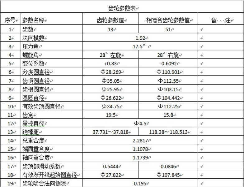
Step 1: We need to extract gear parameters that can completely constrain the gear pair. The table below shows the extracted parameters and their values.
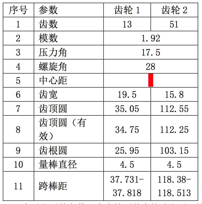
With the above parameters, a gear pair is basically determined. You may wonder why the basic gear parameters don't include the profile shift coefficient. The profile shift coefficient actually reflects the displacement of an imaginary rack cutter. What is completely affected by the profile shift coefficient is actually only the tooth thickness. The tip circle and root circle are affected by both the profile shift coefficient and the addendum/dedendum coefficients. For cylindrical gears, the indicators we use to evaluate tooth thickness are the base tangent length or measurement over pins. So we only need to know the base tangent length or measurement over pins to determine the gear's profile shift coefficient. Students who still don't understand can check the calculation formulas for base tangent length and measurement over pins — does it involve any other cutter-related parameters besides the profile shift coefficient? This also reminds some engineers that in actual gear processing, the profile shift coefficient also has a tolerance band concept. Different base tangent lengths correspond to different profile shift coefficients.
After completing Step 1 parameter extraction, we discovered two issues in this example:
Center distance was not provided. Center distance is very important in gear parameters — it affects contact ratio, sliding ratio, backlash, tip clearance, interference conditions, etc. Without providing center distance, it is basically impossible to evaluate whether gear parameters are well designed.
Apart from measurement over pins, no tolerances were provided for tip circle, root circle, or center distance. Do you mean the factory should machine according to free tolerances?
If we were the machining factory and needed to help the customer complete the gear drawing, we could only use the customer-provided information to back-calculate the center distance.
Below we use ETAGEAR's verification interface to try to determine the center distance:
Step 1: Open the "Parameter Verification Interface" under the "External Cylindrical Gear" module.
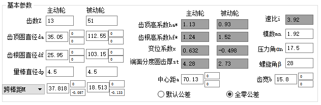
Step 2: Enter the known parameters into the white boxes of the basic parameters:
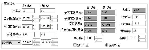
We randomly guessed a center distance of 70. Then clicked the Calculate Parameters button. Let's see what the backlash is?
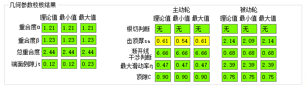
The software gives a transverse backlash of 0.12. The parameter table above gives a normal backlash jn of 0.195, while the software calculates transverse backlash jt. So we need to convert normal backlash to transverse backlash.
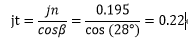
This indicates our given center distance is too small. We gradually increase the center distance until the transverse backlash reaches 0.22 — when we increase the center distance to 70.13, the transverse backlash is 0.22mm.
The above is the approach when the customer cannot answer anything. Ideally, it's still best to directly ask the customer what the actual center distance is.
Here we temporarily proceed with 70.13 for subsequent parameter calculations.
Now let's check whether this set of gear parameters has problems based on the criteria introduced above:
- Completeness of gear parameters — calculate tip tooth thickness of both gears.
The user's gear parameters include both a tip circle parameter and an effective tip circle parameter, indicating that the gear tip will have rounding or chamfering. So we need to look at the gear drawing to see how the tip is treated. What we can determine is that the involute ends at the effective tip circle. Here we discover Issue 3 with these parameters: tip modification is indicated, but the specific modification shape is not specified.
To verify the completeness of gear parameters, we need to use the tip circle, not the effective tip circle. The tip tooth thickness we calculate using the formula will definitely be larger than the actual tip tooth thickness, but if the calculated tip tooth thickness is already unsafe, then this gear is definitely unsafe. Since the poster did not provide drawings, and we don't know how this gear pair's tips are treated, we can only use this approximate method for verification.
With tip circle values of 35.05 and 122.55, the results show their tip tooth thicknesses are 0.54-0.61 and 2.09-2.14 respectively.
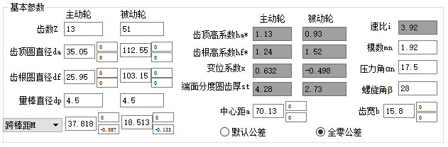
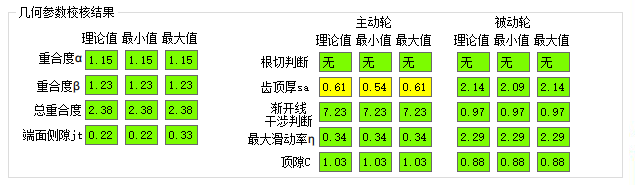
Gear 1's minimum tip tooth thickness is 0.54mm, equivalent to 0.28mn. Gear 2's minimum tip tooth thickness is 2.09, equivalent to 1.09mn. So Gear 2's tip tooth thickness is definitely not a problem. For Gear 1, if it's used for general conventional requirements and is not a hardened gear, there is no problem either. But even if it is a hardened gear, there may not be a problem. As discussed above, every product has its own design background — the poster did not disclose such information, so we cannot determine the evaluation criteria for them and they need to judge based on their own industry background.
- Machinability judgment.
First, this set of parameters does not provide a machining accuracy grade. We cannot arrange a reasonable machining process. Here we assume the simplest and most common process — hobbing followed by heat treatment. Gear accuracy grade: 8. (Issue 4: no accuracy grade.)
Now we see that this gear parameter set provides both tip circle and effective tip circle parameters, indicating the tip definitely has modification. This basically rules out using a non-topping standard hob. After entering basic parameters and clicking Calculate Parameters, the software helps verify some coefficients in the basic parameters section. For example, this set of gears has addendum coefficients of 1.13 and 0.93, and dedendum coefficients of 1.24 and 1.52. This means these parameters definitely cannot be processed with a standard topping hob. This set of parameters requires a custom-made hob.
- Continuous transmission condition judgment.
Both gears have equal module, pressure angle, and helix angle — they can mesh with each other.
Then we need to calculate the contact ratio. We recommend always calculating contact ratio with tolerances. Because housing accuracies vary across industries, users need to judge based on their own housing machining accuracy whether the gears can meet continuous transmission conditions.
The user did not provide center distance tolerance — we assume ±0.03. In actual calculation, we recommend using 1.5-3 times the housing center distance machining tolerance.
When calculating contact ratio with the tip circle, the effective tip circle should be used. The effective tip circle is where the involute profile ends — this point is needed for contact ratio calculation. The segment between tip circle and effective tip circle is not involute and theoretically does not participate in meshing. The two gears' effective tip circles are 34.75 and 112.25 respectively.
We need to determine the effective tip circle tolerance. As mentioned above, because of tip modification, the hob will machine to the gear's tip — at least the tip modification shape is definitely machined by the hob. So the effective tip circle tolerance calculation can basically follow the topping hob parameter calculation method.
Now we open the "Measurement Over Pins to Base Tangent Length Conversion" function under Common Tools in ETAGEAR gear design software. Enter our known parameters in the input boxes, click Calculate Parameters, and verify that the addendum and dedendum coefficients are correct. Here the author sets the tip circle at 34.75 and root circle at 25.95 when measurement over pins is 37.818. The results are as follows:
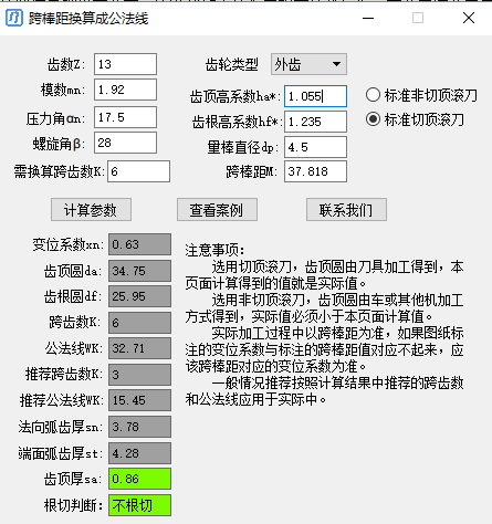
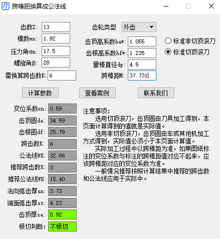
Now we just need to change the measurement over pins from 37.818 to 37.731 to calculate how the tip circle and root circle change when the measurement over pins varies using the same topping hob. After changing measurement over pins, the results are:
Measurement over pins range: 37.818-37.731
Using topping hob:
Tip circle range: 34.75-34.59, i.e., 34.75 (0/-0.16)
Root circle range: 25.95-25.79, i.e., 25.96 (0/-0.16)
Similarly, we need to go through this process for the large gear to calculate its machinable tolerance band.
Large gear measurement over pins range: 118.513-118.38
Using topping hob:
Tip circle range: 112.25-112.1, i.e., 112.25 (0/-0.15)
Root circle range: 103.15-103, i.e., 103.15 (0/-0.15)
Observant students will notice a phenomenon: the profile shift coefficient provided in the case differs from the one calculated from measurement over pins. This is actually very common. Because currently the vast majority of gear design software, including the gear parameter calculation methods published in handbooks, perform design calculations under the assumption that gear backlash is 0. After calculation, engineers often need to manually reduce the calculated base tangent length or measurement over pins to leave clearance for gear meshing. Then the tip circle and root circle are not adjusted accordingly. Because that algorithm defaults to non-topping hobs — the tip circle is turned. So slight variations in base tangent length do not affect tip circle machining. The tip circle can be machined to specification by turning. Then the hob ensures the gear's base tangent length or measurement over pins, and the only dimension machined incorrectly is the root circle. At this point, you will hear many experienced engineers say that the gear's root circle does not need to be dimensioned. Why? Because under this approach, the actually machined root circle will definitely be smaller than the calculated value. If the root circle is dimensioned, it needs to be measured, but with a standard hob, the root circle will definitely not pass inspection. So experienced engineers advocate not dimensioning the root circle. With the progress of time, today's structural design wall thicknesses are increasingly approaching limits, and the root circle dimension's impact on gear strength is becoming more and more significant. So our company advocates dimensioning and controlling the root circle — after structural design is complete, finite element analysis and other methods should be used to assess whether it will affect gear strength. Here's a plug for our software: ETAGEAR's built-in gear algorithm uses an internationally advanced calculation model with backlash — what you see is what you get, no need for engineers to adjust base tangent length based on experience. You will also find that ETAGEAR's recommended profile shift coefficients are adjusted according to backlash changes — you just need to directly mark the parameters you see onto the drawing.
Now back to the main topic. After converting ranges to tolerances and entering them into the software, let the software calculate the contact ratio for this set of parameters.
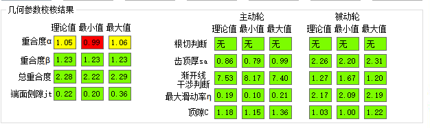
We can see that with tolerances applied, the contact ratio has a risk of being less than 1. But this does not mean this gear pair's parameters are unacceptable, because it has contact ratio in both directions. We consider this gear set to be usable.
Priority order for contact ratio design:
Contact ratio in α direction > 1, contact ratio in β direction > 1
Contact ratio in α direction > 1
Contact ratio in β direction > 1
Total contact ratio > 1
All four situations are considered acceptable for continuous transmission, but try to meet the higher priority levels. For example, in this case, the designer only needs to slightly adjust the center distance to meet priority 1. So this is not considered a problem.
- Smooth gear transmission.
Interference judgment is OK here.
Backlash 0.22 — this varies by industry, but meets general design requirements.
Tip clearance (calculated using tip circle, not effective tip circle) also meets general design requirements.
- Gear life evaluation.
First, looking at undercut: both gears are well designed with no undercut.
Sliding ratio: the two gears' sliding ratios are not balanced, but the maximum sliding ratio does not exceed 3. For Grade 7-8 gear accuracy applications, there should basically be no problems.
Since the case provider did not provide specific operating conditions, the author randomly entered some operating parameters to check the strength distribution. We found that this parameter set basically allocates profile shift coefficients based on equal bending strength design philosophy. This is also a very common design approach when speed is not very high. So there are no issues.
Through the above analysis, I confirm the following issues exist in the provided case:
Center distance was not provided. Center distance is very important in gear parameters — it affects contact ratio, sliding ratio, backlash, tip clearance, interference conditions, etc.
Besides measurement over pins, no tolerances were provided for tip circle, root circle, or center distance.
How the tip modification is done was not specified.
Gear accuracy grade was not specified.
Judging by general gear transmission standards, your parameters lack the above items — their uses have been introduced above. Whether there are other issues by your industry's standards requires your own judgment.
Next, we introduce how to determine your own gear parameter evaluation standards as a company.
- As a company, how do we determine evaluation standards?
Different industries and products have different evaluation standards for gears. So how do we know the specific evaluation standards for gears in a particular industry or product type?
The answer is reverse engineering. This does not mean simply copying others' parameters, but analyzing the design philosophy and evaluation standards from excellent products. This way you can combine your own strengths to create products with selling points.
Below are the specific steps for analyzing gear design philosophy:
- First, measure the following basic gear parameters:
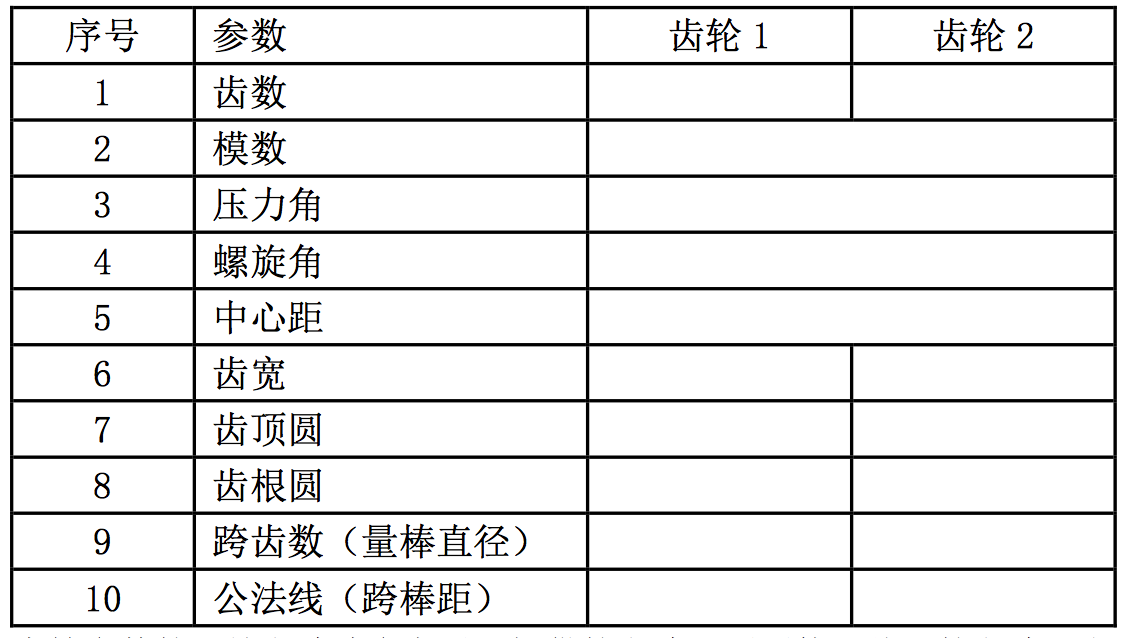
For gear parameter measurement methods, please refer to handbook methods. Do not use estimation methods — all the above parameters can be accurately measured. If you don't know the measurement methods, you can ask us or other professional organizations to help measure or provide training.
- Verify the measured gear parameters. We recommend verifying the following parameters:
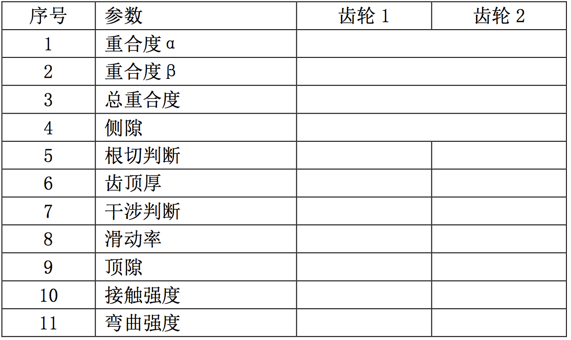
Measure the gear accuracy and examine the tooth profile and lead conditions. Analyze whether modification was performed and the modification amounts.
Analyze the gear's machining process characteristics. This work is particularly important for gears with multiple machining operations on the tooth surface — the design of cutter parameters in each operation has a very significant impact on the gear's final performance.
You can measure multiple products from the same brand to extract that company's design philosophy. Also measure products from multiple different brand companies to see which values are the same and which differ. The differences are often the distinguishing points of each company — invest effort in research and leverage your own enterprise's advantages to create distinctive features.
The general steps for establishing evaluation standards are the four steps above. By repeating these steps and extracting the corresponding evaluation standards, gear design becomes much simpler. Even for foreign gearboxes using the diametral pitch system, we can fully design gear parameters based on domestic standard cutters. As long as Steps 2, 3, and 4 are analyzed well, parameters designed based on these standards will definitely meet usage requirements.
The above is ETAGEAR's understanding of how to design reasonable gear parameters. We welcome everyone's discussion.
If you have questions, please contact us.
E-mail: service@etagear.com