How to process the customers' drawings with only number of teeth and modulus
Classification:External cylindrical gear Author:ETAGEAR Published at:2016-09-04
How to Machine Gears When the Customer Drawing Only Has Number of Teeth and Module
Those in gear machining often encounter customer drawings with incomplete parameters — basically just the number of teeth, module, and pressure angle, and that's it. We know such gear parameters are incomplete. Experienced manufacturers usually reject such orders because if you put together parameters from a gear handbook and machine accordingly, the probability of problems during assembly is very high. Since the drawing parameters are incomplete, you need to be responsible not only for the correctness of gear machining but also for the correctness of the gear parameter design you provide. With so little information from the customer, getting it right is not easy. So what should we do?
Let's look at a specific method using an example the author encountered:
A user wanted to machine gears based on these two drawings:
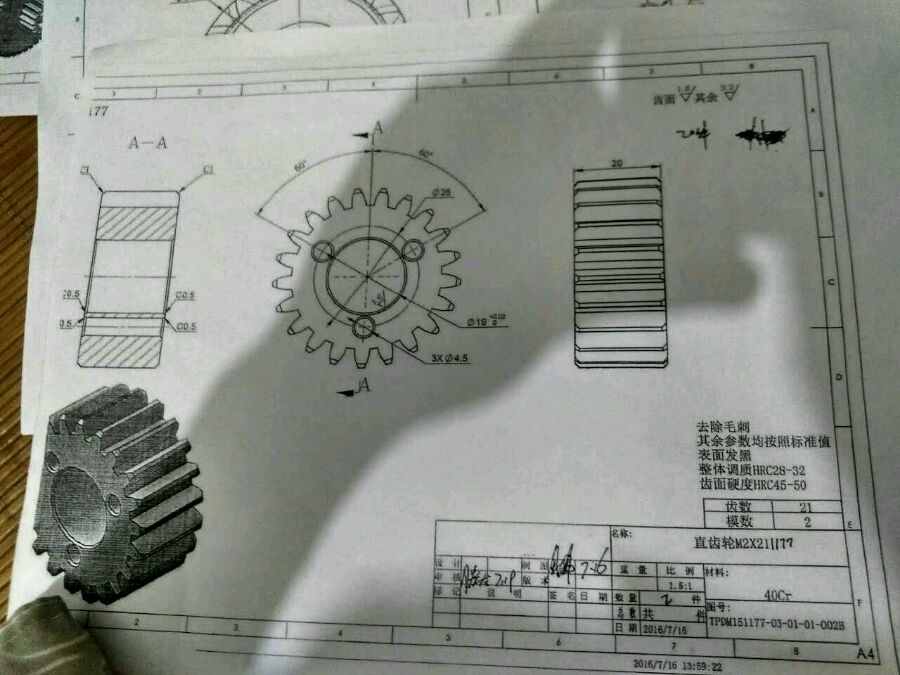
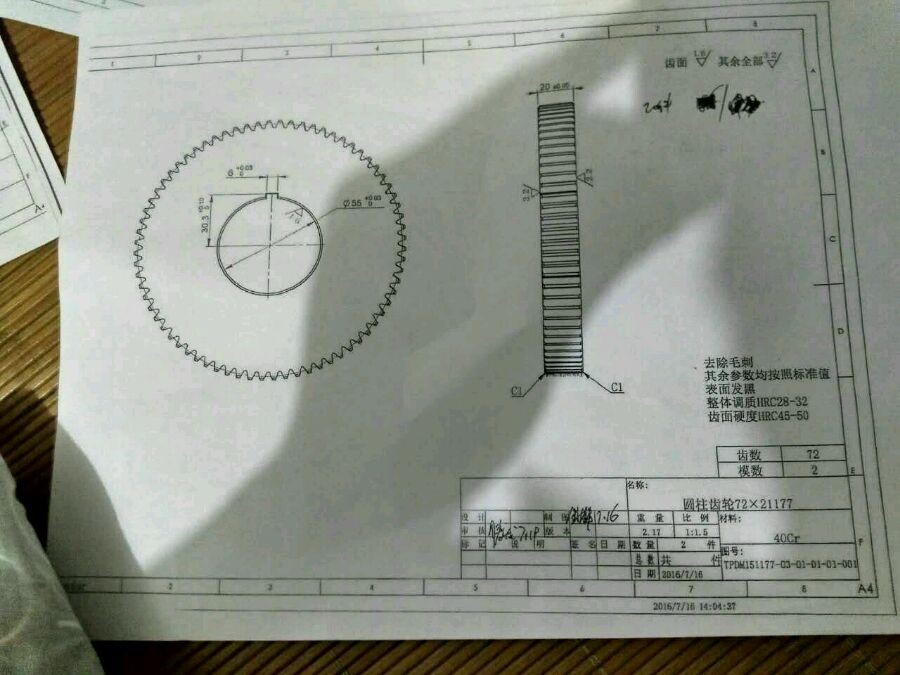
Besides knowing the number of teeth 21/72, module 2, and face width 20, there is basically no other information. We need to complete the parameters. Below I use the advanced function module of ETAGEAR gear design software to complete the relevant information.
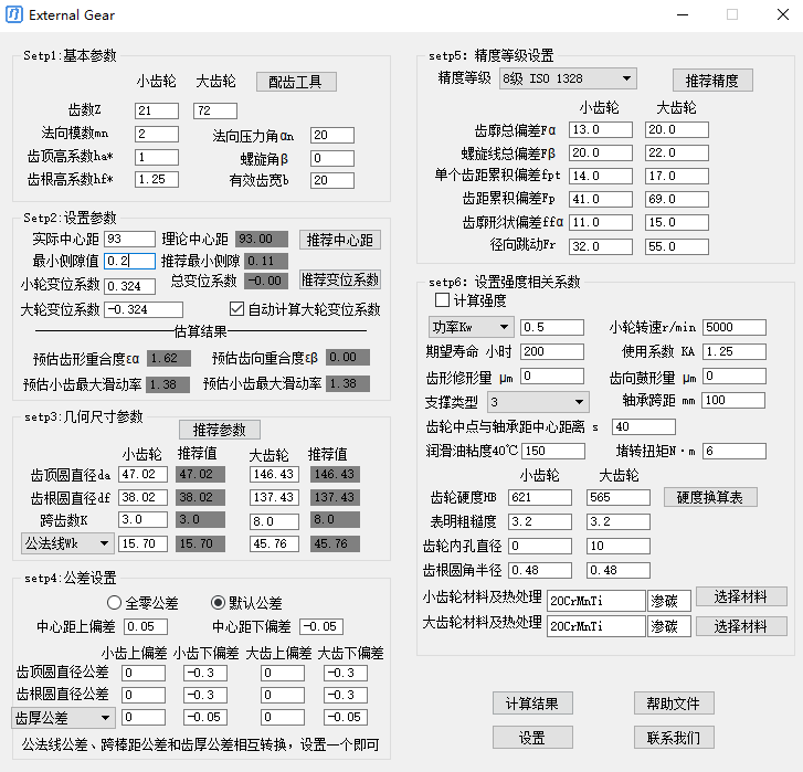
Step 1: Enter the basic parameters:
Number of teeth 21, 72; module 2; pressure angle 20° (standard value); addendum coefficient = 1 (standard value); dedendum coefficient = 1.25 (standard value); helix angle = 0° (the drawing shows spur gears); effective face width 20.
Step 2: In the parameter settings box, click Recommend Center Distance. The software will recommend parameters based on Step 1 inputs. Here we need to change the actual center distance to equal the theoretical center distance, because customers who send such drawings don't know much about gears — they definitely designed using standard gears. In standard gear design theory, the center distance equals the theoretical center distance. This must not be confused. Set the minimum backlash to 0.1 times the module. If the calculated value is less than 0.15, enter 0.15. Why this value? Because gear motion requires backlash — without it, tooth jamming will occur. If you machine standard gears directly without software calculation, tooth jamming or even assembly failure has a very high probability. This will cause customer dissatisfaction. After setting the minimum backlash, click the "Recommend Profile Shift Coefficient" button to let the software allocate profile shift coefficients.
Step 3: For the geometric dimension parameters section, simply click the Recommend Parameters button. The software will calculate all parameters for you.
Step 4: Tolerance settings. Enter tolerances based on your factory's design and machining capability. Zero tolerances are not recommended here, because improper tolerances can also cause problems — the software will check for risks when you enter them.
Step 5: Accuracy grade setting. The software has a gear accuracy recommendation function. Different gear accuracies require different machining methods. If the customer's gear has high linear velocity and you choose an inappropriate machining method, the gear will have obvious noise and wear problems. Click the Recommend Accuracy button, enter the relevant parameters in the popup dialog, and the software will automatically select the appropriate gear accuracy.
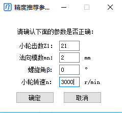
Strength calculation requires many parameters, and the customer probably can't figure them out, so we skip strength calculation. At this point, it's essentially done. Click the "Calculation Results" button at the bottom to get the detailed parameter table. To judge whether the results are good, just check if there are any red warnings in the geometric parameter verification results. In this example, the results are very good — we can machine the gears directly according to the calculated results.
We can click Save Parameters to save the results.
In the above process, we need to confirm 2 values with the customer: one is the mounting center distance — such customers usually choose the standard value — and the other is the driving gear speed, used to determine the gear accuracy grade.
From the calculation results above, you can see they are very good and can basically be confirmed as suitable for the customer's use.
Software download: https://www.etagear.com/download.html