

Explanation on the basic parameters and design of gears
Classification:External cylindrical gear Author:ETAGEAR Published at:2016-09-04
Basic Gear Parameters and Design Guidelines
Author: ETAGEAR Chief Gear Technology Officer, Mao Guoxing
This article mainly answers two questions:
- What are the basic parameters of a gear?
- How do we evaluate a gear during design?
What are the basic gear parameters? To fully define a gear, the basic parameters that must be specified include: number of teeth, normal module, normal pressure angle, helix angle, face width, tip diameter, root diameter, span number, base tangent length (span number and base tangent length can be replaced by measurement over pins/balls), and center distance. You might wonder why the profile shift coefficient is not included. Below we will introduce the significance of each parameter and explain why we should specify the base tangent length rather than the profile shift coefficient.
Number of teeth, symbol Z — the total number of teeth around the entire circumference of the gear.
Normal module, symbol mn. In addition to the normal module, there is also the transverse module, symbol mt. For spur gears, the normal module equals the transverse module. For helical gears, their relationship is:

Where β is the gear helix angle.
The normal module refers to the module of the cutting tool used to machine the gear, measured in the plane perpendicular to the helix angle generator line. The transverse module refers to the gear module measured in a plane parallel to the gear end face.
The module m itself has no physical meaning. Its purpose is to replace the gear pitch P:

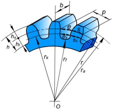
Once the module m is determined, the individual tooth thickness is essentially defined. Combined with the number of teeth Z, the overall size of the gear is basically determined. The module m affects gear strength — both tooth breakage and wear can be improved by increasing the module.
Normal pressure angle, symbol αn. The pressure angle is the angle between the direction of involute motion and the direction of the applied force. The pressure angle varies at different points on the involute — the farther from the base circle, the larger the pressure angle. At the base circle, the pressure angle is 0°. In most countries worldwide, the pressure angle at the pitch circle is 20°.
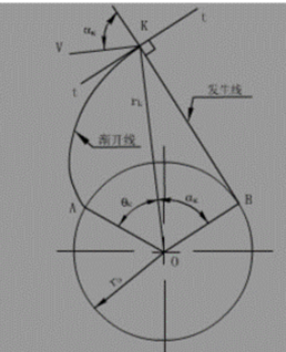
An important concept to understand: the pressure angle differs at different points on the gear. Therefore, when people say changing the pressure angle can alter the contact ratio or strength, they are correct. However, the principle works by adjusting the shape of the involute to optimize gear transmission. In general, the same effect can be achieved by adjusting the profile shift coefficient. Changing the pressure angle requires replacing the cutting tool, while adjusting the profile shift coefficient only requires changing the tool position. Therefore, under normal circumstances, if optimization can be achieved through profile shift coefficient adjustment, we use that approach. Changing the pressure angle is only considered when profile shift coefficient adjustment cannot achieve the goal, since custom tools have long lead times and higher costs.
Helix angle, symbol β. The acute angle between the tangent line of the helical line on the pitch cylinder and the axis of a helical gear is called the helix angle.
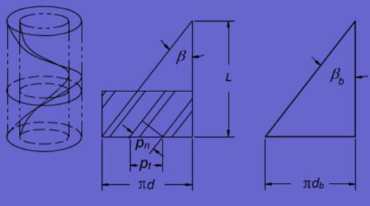
The advantage of helical gears over spur gears is that helical gears have a larger contact ratio, improving both strength and smoothness. Therefore, at the same manufacturing precision, helical gears are suitable for higher rotational speeds. Spur gears have a helix angle of 0. Of course, the disadvantage of helical gears is that meshing generates an axial force component, making axial positioning requirements much higher than for spur gears.
Face width, symbol b — the width of the toothed portion measured along the straight generator line of the pitch cylinder.

The face width affects the contact ratio of helical gears. Since it also affects the contact area, it influences gear strength as well. Ideally, a longer face width provides greater strength improvement. However, in practice, due to manufacturing errors, a longer face width leads to larger error accumulation, causing increased meshing impact and reduced gear strength. Therefore, selecting an appropriate face width is essential — the belief that longer face width always means better strength is incorrect.
Tip diameter, symbol da — the circle passing through the tips of all gear teeth. The diameter is denoted as da and the radius as ra. The tip diameter is very important in gear parameters — its value affects the contact ratio, sliding ratio, tip thickness, etc. Improper values can even cause gear meshing interference.
Root diameter, symbol df — the circle tangent to the bottom of all tooth spaces. The diameter is denoted as df and the radius as rf. The root diameter affects gear tip clearance. It influences the stress concentration location at the tooth root, and for thin-walled gears, this value has a very significant impact on bending strength. Many people think this value does not need to be specified, but we strongly recommend marking it on drawings for easier troubleshooting. However, machining control of the root diameter does not need to be strict, since the root diameter is determined by the tool and base tangent length. Once the first machining is correct, the probability of subsequent errors is very small. But if this value is overlooked and problems occur, responsibility between you and the manufacturer becomes difficult to determine.
Span number, symbol k. Base tangent length, symbol wk. The span number and base tangent length are essentially one physical quantity. The base tangent length is the distance between two parallel planes tangent to two opposite tooth flanks. It can also be understood as the distance across k teeth measured with a base tangent length micrometer. The figure below shows the base tangent length W spanning 3 teeth.
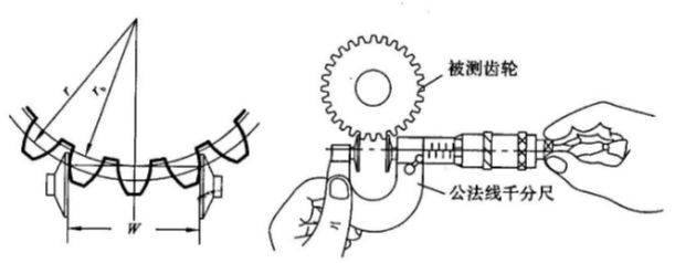
The purpose of measuring the span number is to determine the gear tooth thickness, which can also be considered as measuring the gear profile shift coefficient. In actual gear machining, we measure the base tangent length rather than focusing too much on the profile shift coefficient. The profile shift coefficient represents the tool offset distance, but it cannot be directly measured on the gear, whereas the base tangent length can be measured directly. From it, we can calculate the exact value of the profile shift coefficient. It is important to understand that the profile shift coefficient also has a tolerance range.
The last parameter is center distance, symbol a'. The center distance is the distance between the axes of two gears, i.e., the installation distance between gear axes. For gear beginners, the standard center distance a is often mistakenly used as the actual center distance a'. However, in engineering practice, gears undergo angular modification, mostly positive modification, meaning the actual center distance a' is generally greater than the standard center distance a. The choice of center distance affects the selection of individual gear profile shift coefficients, and also impacts the contact ratio, sliding ratio, interference conditions, etc. The center distance does not affect a single gear, but it has a very significant impact on the smoothness and strength of the gear mesh.
The parameters described above are items that must be marked on gear drawings. Otherwise, your gear parameters are incomplete. Incomplete gear parameters leave many possibilities, and if handed to a gear manufacturer without deep gear knowledge, your gears are likely to have problems or may even be impossible to assemble.
The above tells you the basic gear parameters — when they are properly annotated, the gear parameters are complete. Below we introduce the indicators to check during the gear design process.
Undercutting check — During the generation machining of involute gears, the tool tip sometimes cuts away part of the involute tooth profile at the root of the gear being machined. The drawback of undercutting is weakened root strength, and it may even reduce the transmission contact ratio, affecting transmission quality. Although undercutting has adverse effects, some companies now deliberately use undercutting to counteract involute interference. When undercutting exists, the root bending strength value calculated by software will be larger than reality, requiring the engineer to make their own judgment. Note especially that undercutting does not absolutely mean it is prohibited — it depends on the actual situation.
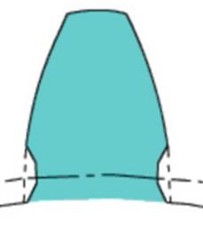
Tip thickness, symbol sa — the arc length at the top of the gear tooth. The purpose of this value is to ensure the completeness of the tooth form. How to understand this? When the profile shift coefficient increases, the gear tip becomes increasingly pointed. If this value is not checked, the engineer may overlook it, resulting in a tooth tip that cannot be manufactured — meaning the tip diameter cannot be machined to the required dimension. Then the calculated contact ratio, sliding ratio, etc. would be incorrect. Additionally, a pointed tip can cause tip chipping due to meshing impact forces. Once these particles enter the tooth surface, the gear will wear very quickly. Therefore, tip thickness calculation is very important. Generally sa ≥ 0.25mn is required; for surface-hardened gears, sa > 0.4mn.
Contact ratio, symbol ε — the magnitude of the contact ratio indicates how many tooth pairs are simultaneously in mesh. For example, ε = 1 means only one pair of teeth is in mesh throughout the transmission. For ε = 1.3, as shown in the figure, in the actual line of action segments B2A1 and A2B1 (each 0.3Pb long), two pairs of teeth are simultaneously meshing (double-tooth contact zone); while near the pitch point P in the A1A2 segment (0.7Pb long), only one pair of teeth is meshing (single-tooth contact zone).
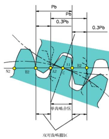
A larger contact ratio is generally better. During design, to ensure continuous smooth gear rotation, if gear tolerances are included in the calculation, the minimum contact ratio should be greater than 1.05. If tolerances are not included, the contact ratio should be at least greater than 1.2.
Sliding ratio, symbol η — the sliding ratio is the velocity difference between two meshing points during gear engagement. Its magnitude affects gear wear and heat generation. During design, we calculate the maximum sliding ratio, which occurs where the gear tip meshes with the mating gear. Fewer teeth tend to result in larger sliding ratios. We recommend the sliding ratio not exceed 3, and absolutely not exceed 5. The sliding ratio is very important for high-speed gears; at lower linear velocities, requirements can be somewhat relaxed.
Backlash, symbol jn — during gear mesh transmission, to form a lubricating oil film between meshing tooth profiles and to prevent seizure from thermal expansion due to tooth friction, clearance must be maintained between tooth profiles. This clearance is called backlash. However, the existence of backlash causes inter-tooth impact, affecting gear transmission smoothness. Therefore, this clearance must be very small, typically ensured by gear tolerances. Higher precision gears and housings allow smaller backlash; otherwise, appropriate backlash must be maintained. In the design process, we have a parameter called minimum backlash — the allowable backlash under static conditions when a gear with maximum allowable effective tooth thickness meshes with a mating gear also having maximum allowable effective tooth thickness at the tightest allowable center distance. Note that minimum backlash is calculated with tolerances, not theoretical values. For general engineering applications, the recommended minimum backlash is calculated using the following formula:

Tip clearance, symbol c — the clearance between one gear's tooth tip and the mating gear's tooth root during meshing. It is mainly controlled by the tip clearance coefficient. During design, be careful not to make tip clearance too small; otherwise, impacts may occur when the center distance changes. Tip clearance also serves an oil retention function, so maintaining appropriate tip clearance is necessary. Generally, controlling tip clearance at 0.25mn is sufficient.
Involute interference check: When one gear's tooth tip contacts the transition curve at the root of the mating gear, a constant transmission ratio cannot be guaranteed. This is called transition curve interference. This interference may occur when the absolute value of the selected profile shift coefficient is too large. This phenomenon is very common with small tooth numbers. Once it occurs, obvious wear appears at the pinion root and the mating gear tip. If operation continues, it will progress to wear across the entire tooth surface. Involute interference must be eliminated during design. Some engineers believe that undercutting the pinion can eliminate involute interference — this is not entirely correct. Careful calculation is needed to confirm whether involute interference has been eliminated.
With the knowledge of the above parameters and using our calculation software, you can complete professional gear design. Below is an overview of the design process:
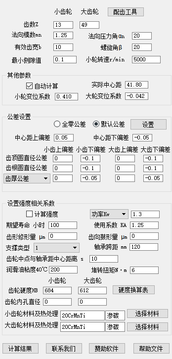
Determine the number of teeth, module, pressure angle (20°), face width, helix angle (0° for spur gears; typically 8–20° for helical gears, preferably not exceeding 35°). Set the minimum backlash value and input the pinion speed. Here is a specific example: teeth 13/49, module 1.25, pressure angle 20°, face width 10 mm, helix angle 20°, minimum backlash 0.1, pinion speed 5000 rpm.
Check "Auto Calculate" in the other parameters section.
Enter machining tolerances in the tolerance settings — generally determined by the machining method and supplier capability. For theoretical calculations only, set all tolerances to 0.
If the module references a prototype or previous product, strength calculation may not be necessary — simply uncheck the strength calculation option.
Click the "Calculation Results" button at the bottom to complete the parameter calculation.
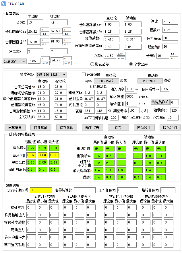
How do we evaluate whether the parameters are good? Simply look at the color indicators in the middle of the table: green indicates no issues; yellow requires engineer judgment — generally yellow values are still acceptable unless high-precision gear transmission is required. Click "Save Parameters" to save the parameters to a file for convenient future access. With the parameters, we can proceed to generate drawings — for specific drawing procedures, refer to related articles on our website.
If you have any questions, please send an email to service@etagear.com. We will do our best to serve you.