

The Physical meaning and optimization algorithm of the tip alteration coefficient
Classification:FAQ Author:ETAGEAR Published at:2018-06-12
Physical Significance of the Addendum Modification Coefficient and Algorithm Optimization Notes
Recently, customers have raised the question: Why doesn't your software use the addendum modification coefficient when calculating the addendum height?
Key Response: Because many gears today are manufactured using topping cutters. Including the addendum modification coefficient in the addendum height calculation causes the calculated tip circle to not correspond to the actual machined tip circle. Should the machined gear then be considered conforming or non-conforming? To machine according to the calculated values, one would have to use non-topping cutters, thus losing the advantages of topping cutters.
Would removing the addendum modification coefficient cause any problems? The handbook formulas have been used for so many years — what is your basis for the modification?
Let us first review the previous question: Why is the profile shift coefficient calculated by ETAGEAR different from that calculated using the handbook?
Key Response:
The physical significance of the profile shift coefficient is that it represents the displacement of the standard cutter.
To machine gears of different tooth thickness (span measurement values), the cutter position is shifted. Different tooth thicknesses correspond to different cutter positions, so the profile shift coefficients for different tooth thicknesses (span measurements) must be different.
The handbook algorithm assumes zero backlash, while ETAGEAR uses an algorithm with backlash. At the same center distance, with different backlash values, the gear tooth thickness must be adjusted, so the profile shift coefficient with backlash must differ from that with zero backlash, and different backlash values will yield different profile shift coefficients.
To understand the basis for removing the addendum modification coefficient, we need to understand its physical significance.
The addendum modification coefficient is used to calculate addendum height:
ha=(ha*+x1-Δy)m
The addendum modification coefficient exists to change the addendum height — but why change the addendum height? It is actually to ensure the tip clearance of the gear mesh. Tip clearance is the gap between the tip of one gear and the root of the mating gear. Typically, the handbook specifies a tip clearance coefficient C*=0.25, and changing this value changes the tip clearance C, where C=C*m.
Let us see how the handbook algorithm ensures the tip clearance is exactly C*m=0.25m:
The formula for tip clearance is not explicitly given in the handbook. Based on its definition, we know: Tip clearance = Center distance - 0.5×(da1+df2).
The tip clearance calculation process is as follows:
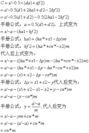
Where: a' = actual center distance, a = theoretical center distance, C = tip clearance, da1 = driving gear tip circle, df2 = driven gear root circle, d1 = driving gear pitch circle, d2 = driven gear pitch circle, ha1 = driving gear addendum height, hf2 = driven gear dedendum height, ha* = addendum coefficient, x1 = driving gear profile shift coefficient, x2 = driven gear profile shift coefficient, Δy = addendum modification coefficient, m = module, cn* = tip clearance coefficient, y = center distance modification coefficient.
The above is essentially the derivation process of the addendum modification coefficient. Introducing the addendum modification coefficient in the addendum height calculation ensures the gear mesh tip clearance is the fixed value Cn*m. This is why the handbook has no tip clearance calculation formula — and as shown above, the handbook algorithm does not need to verify the tip clearance value, because gears calculated using the handbook method always have a fixed tip clearance.
In that era, the standard cutter addendum coefficient was 1.25, and the dedendum coefficient was also 1.25. As long as the gear's addendum coefficient did not exceed 1.25, the gear tip circle would not be cut by the cutter. The gear tip circle was finish-turned before gear cutting. With this machining process, as long as the addendum coefficient did not exceed 1.25, the tip circle could be adjusted within a small range. So introducing the addendum modification coefficient to ensure adequate tip clearance did not affect machining, while also preventing operational failure due to insufficient tip clearance — an excellent design choice.
However, with advances in cutter technology, modern gear cutters can now cut not only the root circle and tooth flanks, but also the tip circle without affecting cutter life. Whether the cutter cuts the tip circle has a significant impact on the final gear precision. Gears with tip circles cut by topping cutters have significantly better cumulative pitch error Fp than those machined with non-topping cutters. With non-topping cutters, the tip circle is finish-turned and the tooth profile is generated separately — though they share the same locating bore, the fixtures and machines differ. This causes concentricity deviation between the tip circle and pitch circle. When grinding the bore, we actually need to reference the pitch circle, but pitch circle fixtures are complex and have poor force distribution. Referencing the tip circle directly is problematic because the tip circle and pitch circle are machined separately, each with its own concentricity error, compounded by the bore grinding error. The result is often that while the tooth profile Fα and helix Fβ are acceptable, cumulative pitch Fp is too large and unstable. This is common with non-topping cutters. With topping cutters, the tip circle and tooth profile are machined with the same fixture on the same machine simultaneously, achieving very high concentricity. Subsequent bore grinding can reference the tip circle with results very close to referencing the pitch circle. The resulting Fp is small and consistently stable.
In summary, switching to a topping cutter improves gear machining precision at almost no additional cost, which is why more and more companies are adopting topping cutters. Small-to-medium module gear production has largely switched to topping hobs.
Under these circumstances, introducing the addendum modification coefficient becomes problematic. If I machine gears using the handbook-calculated tip circle, the cutter addendum coefficient should be ha*-Δy. We know Δy is influenced by center distance and not a fixed value, so every gear with a different tip circle would require re-specifying the cutter. This negates the benefits of cutter standardization. If I use a standard cutter directly, the machined gear's addendum coefficient would be ha*, which differs from the handbook's ha*-Δy. The gear could easily be judged non-conforming. If I ignore this value and use whatever comes out, only heaven knows whether the gear will have problems.
To adapt to the times, ETAGEAR decided to remove the addendum modification coefficient and calculate the addendum height directly, which better aligns with actual production. Removing it makes the calculation applicable to both topping and non-topping cutters: our gear ha*=1, still less than the non-topping cutter standard of 1.25, so machining is not affected. The removal of the addendum modification coefficient has already been applied in most international gear software for many years.
The biggest issue with removing the addendum modification coefficient is the risk of tip clearance interference. So if the algorithm removes the addendum modification coefficient, it cannot 100% guarantee that tip clearance always exists and is reasonable. Therefore, we must verify the gear tip clearance. Removing the addendum modification coefficient brings several changes:
Gear tip clearance must now be verified, since the new algorithm does not yield a fixed tip clearance. Tip clearance becomes like backlash — it needs to be verified and manually evaluated. Based on our practical verification, over 99% of gear applications have no tip clearance issues. Only in rare cases with extreme profile shift coefficients is the tip clearance too small and requires adjustment.
The tip clearance coefficient is no longer recommended; use the dedendum coefficient instead. The original algorithm's tip clearance coefficient could precisely control gear mesh tip clearance. But after removing the addendum modification coefficient, the tip clearance coefficient no longer directly corresponds to the actual tip clearance. To avoid misunderstandings, our software uses the dedendum coefficient instead, where dedendum coefficient = addendum coefficient + tip clearance coefficient.
Through these two changes, we can make the algorithm align with modern machining technology — applicable to both topping and non-topping cutters — while ensuring the designed gear parameters are safe and reliable.